
The best way to learn how to repair a clock is to learn how to make one first – if you know how to make one, you will know the fundamentals necessary to repair one. In addition, some repairs require parts to be replaced which would require making them since, in general, replacement parts are not available.
The first step in making a clock is to decide on some critical design criteria:
1) How long do you want it to run.
2) What is the driving power; weight or mainspring,
3) How large is the clock,
4) What method will be used to regulate the time.
In order to have some commonality in the class a number of these things were decided to be similar; we would have a weight driven clock, using a recoil anchor escapement, running for 30 hours, and a frame approximately three inches wide and five inches high.
The next step is to calculate the general gearing of the clock: Assume that the primary indicator would be a 12 or 24 hour dial (I decided to have a 24 hour dial on the front of my clock) calculate the number of teeth on the wheels and the number of leaves on the pinions. Create a layout of the wheels within the space of the frame.
These calculations can easily be done by hand but I created a small spreadsheet to help with making sure they were correct and to facilitate recalculation as I tried different options.
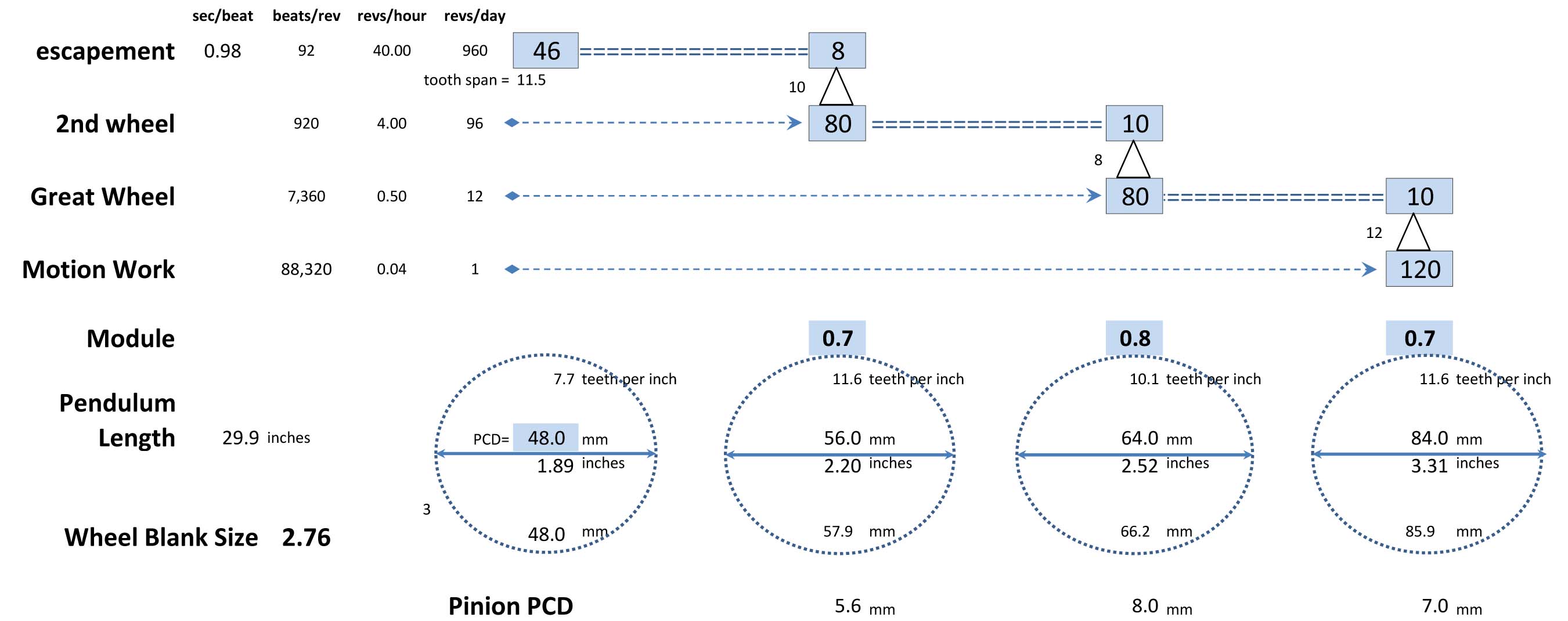
Excel Spreadsheet makes trying different options easier.
You can layout the wheels anywhere as long as the gears mesh properly and the arbors stay inside the frame dimensions that you decided on — I decided to make my wheels line up vertically. You do have to have a good ability to visualize things in three dimensions, so if that is a problem for you, don’t think about trying to be a clockmaker. Engineers use different drawing projections to understand what something looks like from different perspectives. So I drew my clock layout front the front and the side.

Here’s a page from my notebook that show my first pencil drawings of how the clock will be laid out.
Next, it is time to make a little model to see if the general concept makes sense. I drew my design on some stiff cardboard, cut it out and put it together with some tooth picks.

Here’s my model clock without the front plate on – so you can see the wheels.
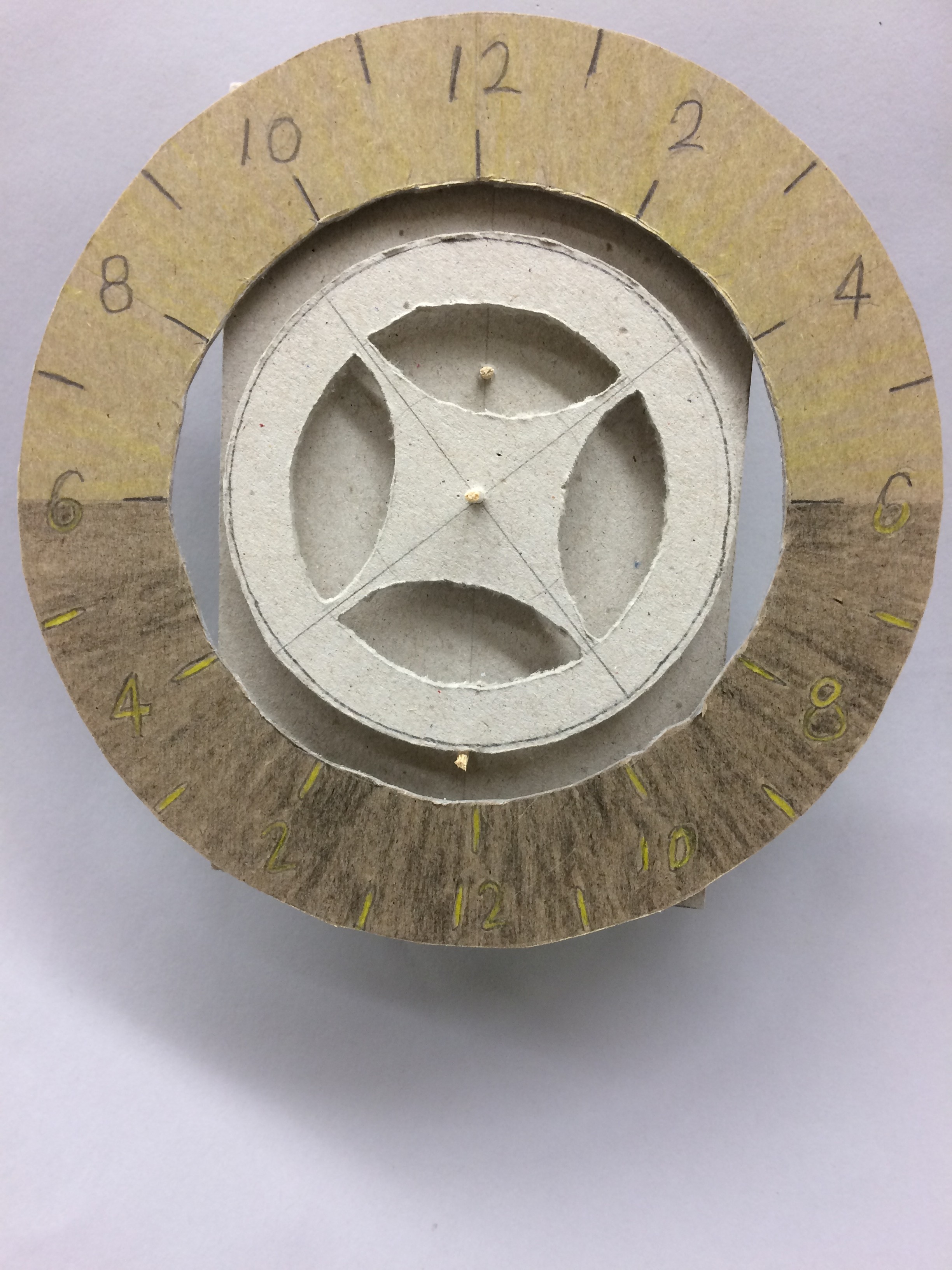
Here is the model from the front. I hope you like it– my dial is going to rotate on the front so there won’t be any moving hands.
Another reason for the model is to live with the idea for a while and see what other things pop into your head. I have already come up with some modifications from this design. Normally a clock would have an hour hand that is connected to the gray wheel in front. It would rotate once per 24 hour day. I am thinking about making the dial revolve instead of an hour hand revolving. I can make teeth on the inside of the dial wheel itself instead of having the large gear in the middle rotate an hour hand.
Well, I would like to say that you will be able to watch this clock come to life over the course of the year–and I hope you will–however, there are other priorities for me, the first being getting my Masters paper written, and second is doing some work on some old clocks–so we will see how far I get with my clock.
keep ticking,
4 comments
Skip to comment form
Mostyn,
Looks like a fun project. I’m jealous. The excel spreadsheet is a great way to go, saves a lot of pencil time and makes it easy to play, what if I change …. However, in the motion works calculation you have a 12 to 1 ratio, shouldn’t it be 24 to 1 for a 24 hour clock?
Hope you and Debbie have a great time in Scotland over the holidays.
Ken
Author
Ken, thanks for making me think about this again. Actually on that spreadsheet, Motion Works is a misnomer because I only have an hour hand, no minute hand. What is labeled Motion works is really just a wheel between the great wheel (that’s the one that will have the weight hanging on it and the hour indication. Just so happens that I decided to make that a 12:1 ratio. I did find another error though. The calculation for the pendulum length is wrong – a seconds beating pendulum should be around one meter long, so the correct length should be 37 inches.
keep up the good clockwork,
Thanks, Mostyn, that was fascinating! I never thought before about how a clock works. Not sure I fully understand now, but it was a good beginning! I look forward to the next installment.
Mostyn, you continue to amaze me! Hope you can get to work on it even though you have other priorities.
Love you, Sue