
The reason I came to West Dean College was to get a Masters Degree in Clock Restoration. Of course, in addition to learning about making and restoring clocks I have to do some research and write a paper for the Masters Degree. Through the year so far, I have been preparing to do the research and write the paper. Of course the first thing is to decide what to write the paper about. I didn’t come to college knowing what I would research but workshop conversations led me to wonder why clock mainsprings get replaced so often. Indeed for some repairers it is routine whether apparently needed or not. From a conservation point of view, this may not be the best practice since throwing away a mainspring is throwing away part of the history of the clock. For many clocks, the history of the mainspring may not be that important, so, no big deal–. But what about the other ones? and how do you know how old the mainspring is? Something that we are being taught to appreciate and look for are the evidences that would help us to verify that it really is an old clock–evidences that would perhaps help the ability to date the clock. A mainspring is perhaps a part of the clock that could help with that, if only you had some way to tell how old the mainspring was. My research is leading to find ways of telling how old a mainspring is.
One part of that research will be understanding the torque that the spring has. This blog post reports on a test set-up that I am using for my MA project paper. So, here’s your chance to opt out of reading this blog–might be too boring.
I have devised a testing jig to measure the torque of mainsprings. It is flexible to be used on multiple mainsprings since I plan to measure around a dozen different mainsprings.
Clock mainsprings are mounted on a winding arbor and enclosed in a barrel.
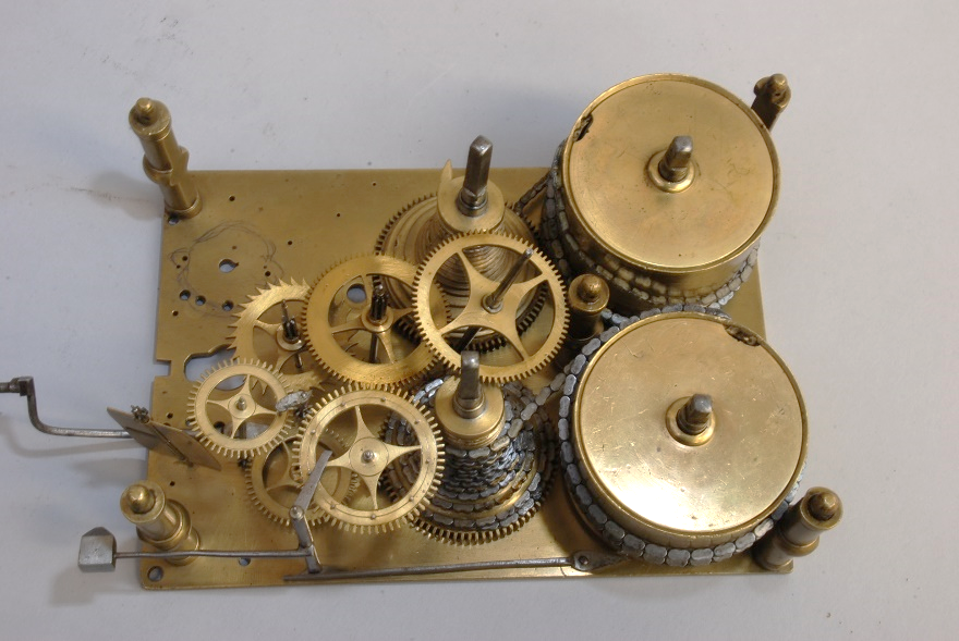
Two mainspring barrels shown on right–square winding arbors are in center of the barrels.
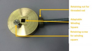
This is the main part of test winding mechanism. The center square is replaceable to fit different size winding squares.
The winding arbor has a square end normally used for winding the clock with a key. This provides a convenient place to attach a winding mechanism for my testing. The objective of my test is to measure the torque and linearity of a mainspring at different degrees of winding tightness. If I remove the mainspring barrel from a clock and clamp it securely, I can attach a measuring tool onto the winding arbor—wind the spring to varying degrees and measure its torque. The results can then be plotted and analyzed to discover the differences between the springs that I intend to research for my Masters project.
Test Setup
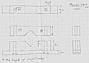
Test jig drawing for the workshop.
I devised a brass disc with a removable center. The center contains a square hole to fit the winding square on the arbor. This center piece can be easily replaced with another of the correct size for different winding arbors. The small square piece is held inside the large disc by a threaded screw.
The large brass disc is also fitted with a long threaded rod about 40 cm in length. This rod need only be thick enough to remain straight when a weight is put on its end.
I gave a test jig drawing to the workshop for them to make of wood and I made the brass and steel parts from scrap pieces in the clock workshop.
The jig also contains some safety features—springs can store a lot of power that, if unlocked inadvertently can be very dangerous—a stop mechanism so that the spring will not be able to unwind all at once and also so that if I need to do anything when the spring is wound, it will stay wound. A second safety feature—not as important—was a knob that I screwed in to the end of the threaded rod. This makes it much easier to wind up and down without potential scratches or cuts to the hands.
Analysis Preparations
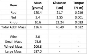
The measured masses and calculated torque for test items.
Before I started trying things out, I wanted to understand what measurements I needed to make and what calculations I would perform with the data.
The equation for torque (T ) is: Torque = force x distance = (mass x acceleration) x distance
We can calculate the torque for my test configuration by knowing the mass added to the threaded rod and the distance it is placed from the center of rotation. In this case, acceleration is that due to the force of gravity, 9.81 m/s2.
Another thing I needed to do before any calculations could be made is account for the forces due to extra mass of parts other than the mass that I placed on the rod, i.e., the mass of the threaded rod, the nut, the hanging wire and the knob. I measured the mass of each part and for those that have a fixed position, I can calculate the torque and add it to the calculated torque at each measured position.
Testing
Now, I set the jig up on my bench in the Clocks Workshop and gave it a try. I first wound the spring completely to see how many turns it would make and then I placed a weight attached to the threaded rod with a piece of wire until the rod balanced in a horizontal position.
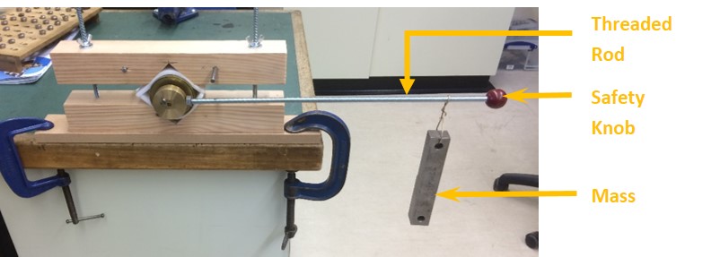
The test jig with the measuring rod balanced by a large mass.
A horizontal position for the balanced bar may seem obvious but it really is not. It is not absolutely necessary but it does make the calculations easier because the force vectors from gravity (on the weight) and from the spring torque are exactly 180° from each other. If this were not the case, I would need to use a vector diagram and trigonometry to help me determine the forces at work.
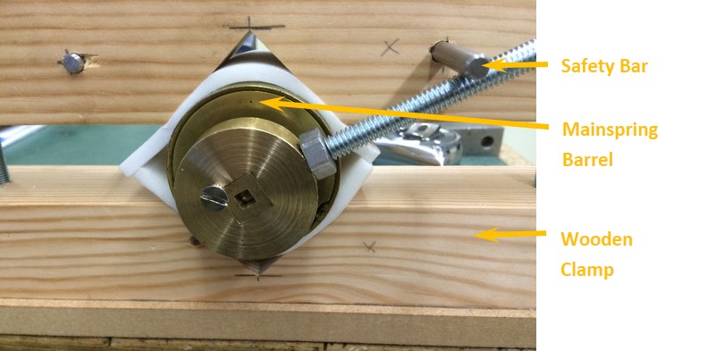
A close-up of test jig shows the safety bar and Plastazote around mainspring barrel to protect it from damage in the clamp.
Finally ready to make some trial measurements, I wound the mainspring as much as it would wind. Since the rod ended up in the lower vertical position after I fully wound the spring, I unwound the spring and moved the winding square 90° counter-clockwise so that a full wind position would be in the right-side horizontal position and I could get a measurement at full wind. I placed the large mass on the rod until it balanced as in Figure 5. I then measured the distance between the center of rotation and the hanging wire for the mass. After writing the distance down, I rotated the rod counter-clockwise one rotation and made another measurement. This I repeated until the mainspring was fully unwound—it was nine turns. On the lower two turns, the mass was quite close to the center of rotation so I changed mass to a lighter mass. I realized afterward that using the smallest mass possible at the farthest position possible is the most accurate because at farther distances a change in position (one thread on the rod I am using) is a smaller percentage of the total distance than if the mass was close to the center of rotation, enabling smaller percentage modifications (more accurate) to the balancing position.
Analysis
I tabulated the data from two runs on Excel and plotted them.
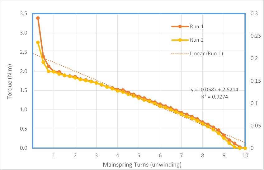 This chart is almost what I expect to see except that it is more linear than I thought it would be. The interpreted linear line shown on the graph shows how the actual torque deviates from perfectly linear. As I test other springs, this will be one point of comparison. The chart shows a high degree of non-linearity as the spring first begins to unwind. As I wound the mainspring I was able to feel that there was friction in the mainspring and barrel as I rotated it with a high number of turns. Also shown on the chart is the equation of the calculated linear regression line and the R-squared value which is a measure of how well the actual data points fit to the straight line. This will be one good way to measure the differences between springs.
The linear regression method of predicting the best linear fit to a group of data points is a method that minimizes the squares of the deviation of all the data points from the proposed line. The R-squared value is the correlation coefficient, i.e., an indicator of how closely the best fit line matches the data points. A perfect correlation would result in a coefficient of value 1, so the R-squared value shown on the chart, 0.9274, shows not great correlation. Probably, I will be eliminating the end points of the curve prior to doing this correlation test–but we’ll see as things progress.
Even though the torque may be very linear (in the middle portion), the chart also indicates the slope of the curve. That means that the torque is not the same as it unwinds. This leads to uneven operation of the clock. To counteract this effect, many mainspring driven clocks in the 15th to 18th century used what is called a fusee. You can see this in the first photo; it is the cone shaped item just to the left of the mainspring barrels. This device was intended to smooth out the torque curve and make it not just linear but constant throughout the unwinding process. That way a clock is more likely to run at an even pace throughout a single wind. I will need to devise an addition to this test jig to be able to test the mainspring and the fusee at the same time to see how well it does the job. The excel spreadsheet and linear regression analysis will enable me to quantify the results.
One aspect of my research will be to understand the impacts of friction in the spring barrel. It is interesting to see that this has already become apparent on the first set of measurements (I suspect that the reduced slope between turns 1 and 4 is due to this friction in the barrel). I plan to clean the spring and to remove sources of friction inside the barrel if possible to see how that changes the torque curve. This is an important conservation issue related to how cleaning can affect the operation of the clock not just its degradation processes or it’s “good looks.”
I will let you know how the testing is going with another report soon.
Thank you to those who stuck out reading through this blog – I hope you learned something – as a reward, here’s a photo of the school workshop just before I take off for home in the evening.
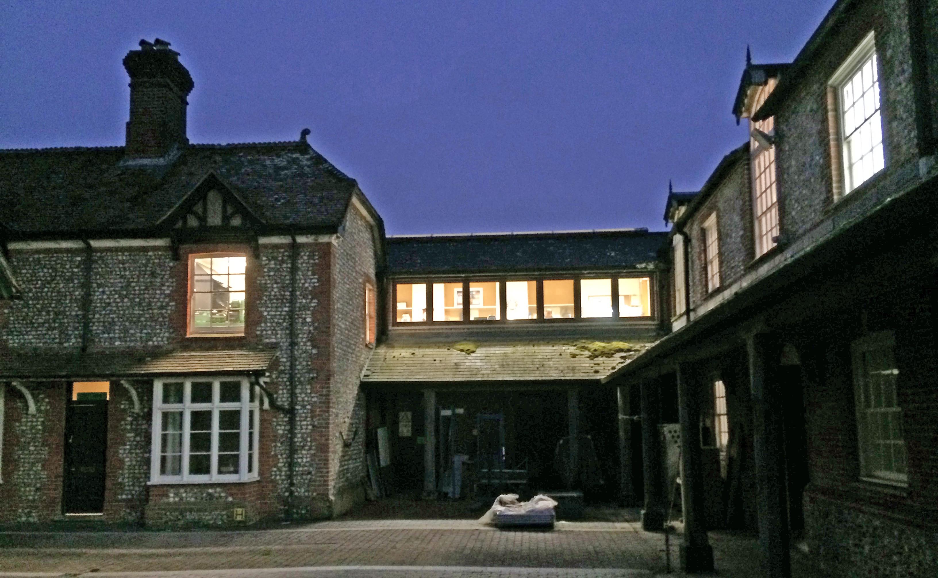
My workbench is just inside the left window of all the windows that are in a row on the second floor.
cheers,
4 comments
Skip to comment form
Mostyn – I found this to be really interesting. It sounds like a great study, and one perfectly suited to your training as an engineer. I’m really curious to see how the fusees do their job. Everyone assumes they solve the problem. But how well do they actually perform? Do you suppose the makers even knew the answers to this question?
Author
Bryan, nice to hear from you. Yes, this is an interesting question that I have never seen any detailed results about. So, I did do a nice experiment and found that fusees do help to improve the consistency but, at least in the one I tested, it did not completely get rid of the dependence on the amount of wind. In addition, it robs the torque y about half, so it is a real trade-off. It turns out that for good quality clocks like chronometers, they did in fact cut the fusee dependent on the exact spring they were going to use. I have seen machines now that mount the spring and cut the fusee dependent on the spring torque at the given wind of the spring. The other thing I learned, which perhaps was obvious to most people but not me, is that the spring is set up to be much longer than needed. In the clock I tested, the spring turned about nine times but the fusee only allowed for six turns. Therefore allowing a person to put a set on the spring at the lowest wind and then if they didn’t wind it up all the it would create a very linear dependence on the amount of wind, but as I said earlier unless the fusee was matched to the fusee, it still is not going to be perfect. I will send you my test results when I get a chance.
cheers,
You are amazing, Mostyn. I read it all through…..but it would take a couple more times, at least to understand it all. How did you do on your evaluation, or don’t you know yet?
Author
My evaluation went well. I have not received the official grade sheet yet but my assessment would be a B+. I am a bit ahead on my Masters work and a bit behind on the practical restoration work. We also had outside people come in who more or less assess the school not so much the individual students, but I received some good feedback from them on my Masters work so far.
Thanks for reading.