Having completed an initial design and tested it with a little model, it is time to move on to real pieces of metal. Well – not so fast – first, make a metal model of the escapement which wasn’t part of the cardboard model I made earlier. This practice for us who aren’t used to working in metal and it is also a good practical test of the design.
First, I made a more precise drawing of the escapement.
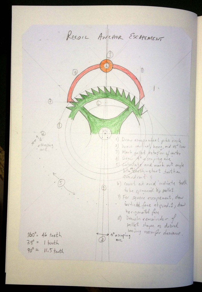
Here’s a page from my notebook. This is called a square escapement – not all are like this but it is an easier place to start.
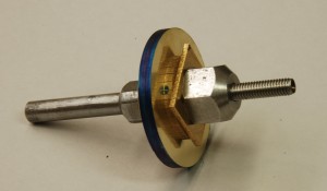
Now it is time for hardware. Start with three squares of brass. After marking and putting a hole in the center, they are mounted in a mandrel (holder) and rounded in the lathe.
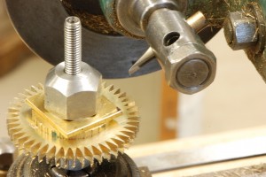
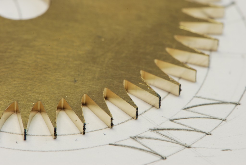
In this picture the cutter is stopped after cutting the teeth so that you can see it in relative position.
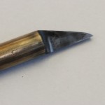
Next I have to make a cutter so that I can cut teeth into the wheel. Now I can put the wheel blanks into the cutting machine and start making teeth.
I next marked and cut out the anchor in brass (because it is easier) so that I can test the escapement design. Sorry I don’t have any pictures of that process.
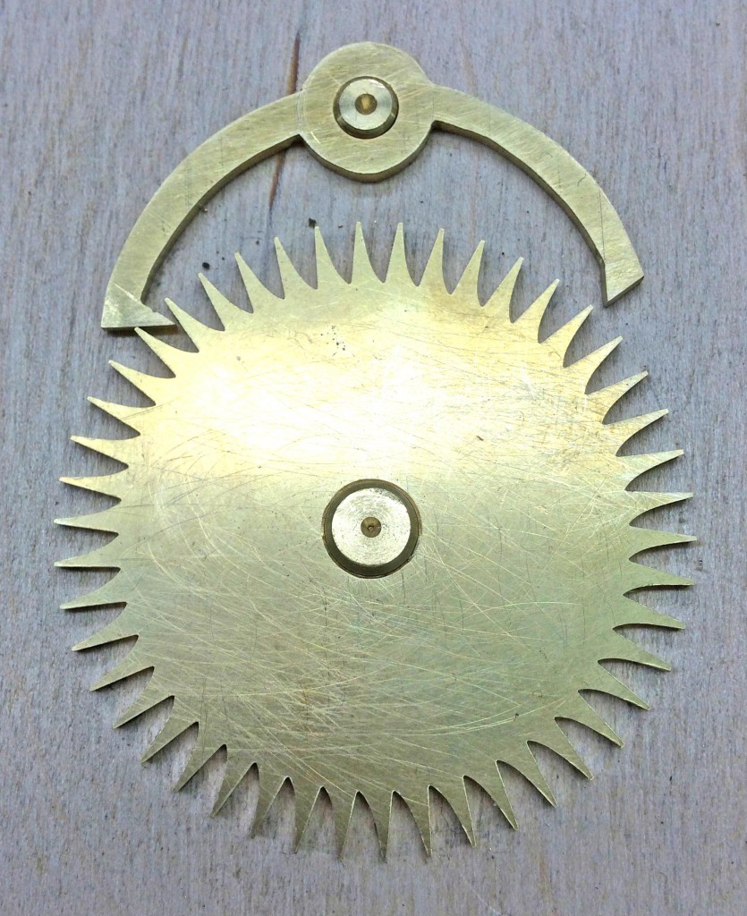
Then, I mounted the wheel and the anchor onto plywood with two brass studs set at the right distance apart. This allows me to test the interaction of the pallets (tips of the anchor) and the wheel. In a real clock the pendulum is connected to the anchor and the tips of the teeth push the pallets which then pushes the pendulum to keep the clock going. So, you can see that this is the heart of a clock – if the teeth do not push the pallets properly, the clock will not run. To give you a sense of size, the wheel is 48 mm in diameter – that’s a little less than two inches for you Americans.
Now I will make the real deal – a brass wheel and steel anchor. After that it will be the plates and pillars.
Stay tuned,

3 comments
Great work, Mostyn. As you say, beautiful, and you explain / write so well. Thanks for taking the time (!!) to share with us. Much love to you both.
Mostyn and Debbie,
Your blogs are so well wriiten and very enjoyable.. Its really neat that we all get tp particpate in your great learning adventure.
Thank You Both
Mike Schmidt
So fascinating to see your work and all it takes to be able to know “what time it is”….and so impressed with the previous inventors (and you!) for coming up with the ideas, and the execution of such precise (and beautiful) workings! Thanks for sharing your great photos, too! All the best to you!!!