In Part 2 of my blog about this project, “What’s a Potence?“, I described making some of the important supporting parts for the wheels. In this blog I have completed two of the wheels to the point that I can put them in the clock and test to makes sure they are going to work correctly. This clock has a center wheel, a second wheel, known as a contrate wheel, and an escape wheel, known as a crown wheel.
The center wheel needed a new pivot, that I described in a previous blog, A Precision Operation, it also needed a new wheel because the reconversion needed a wheel with different number of teeth and a somewhat different shape–that I described in Part 3, Making a Center Wheel.
The contrate wheel is so named because the teeth point sideways instead of radially outwards as they do on a normal wheel. For this wheel I had to make every part; the arbor which contains the pinion and the wheel.
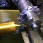
Align the pinion cutter by cutting a slot in the top of a brass cone. Then turn the cone 180 degrees and cut again. If the slots line up perfectly, you are ready to cut the pinion leaves in steel.
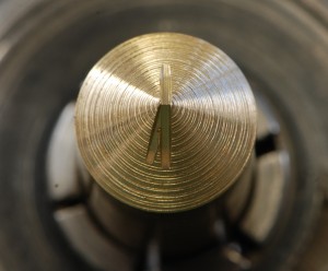
Here’s the brass cone from the end. The slots line up pretty well but perhaps not good enough in this case.
To make a pinion you first take a blank piece of steel rod and cut it to the diameter of the finished pinion. Then there is a careful alignment step where you make sure that the pinion cutter is exactly at the top center of the steel rod. Having that aligned, you can cut the pinion teeth, or leaves as they are correctly called.
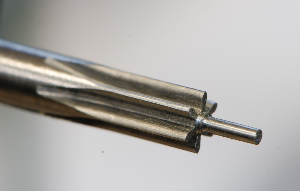
The finished pinion – well not quite finished, it will still need to be polished but it is finished enough to test.
After cutting the pinion, the next step is to check and make sure that it mates correctly with the wheel that drives it. In this case the center wheel drives the pinion of the contrate wheel. The best tool for this is something called a depthing tool. You could put the wheels between the clock plates but many times the holes in the plates are either too large (sloppy) or in the wrong place (improper depthing). The depthing tool allows you to adjust the distance between the two arbors very precisely so that you can find the best distance apart. When I did this I found that the wheel turned nicley in one direction but not the other and of course it was the direction I needed it to turn that didn’t work out so well. So I went to work with a stone taking very small amounts of metal off the leaves in order to reshape them. Apparently, what happened is that when I cut the pinion leaves they were not exactly in the top center of the steel rod. Those slots in the brass cone were not exactly lined up–this is very hard to get exact. After about three hours of stoning and checking I got it perfect. This operation is made more difficult because the pieces are small–the pinion is about 1/4 inch in diameter and the teeth are about 1 mm wide. (By the way, I have gotten really good as switching back and forth between mm and inches).
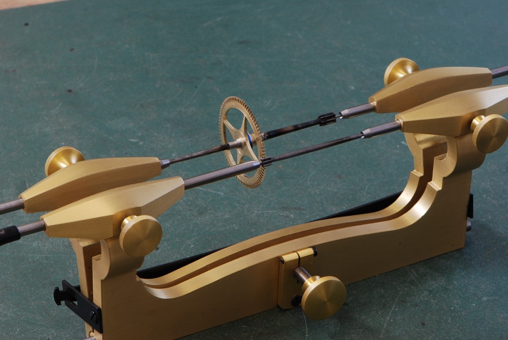
The contrate arbor and the center wheel in the depthing tool.
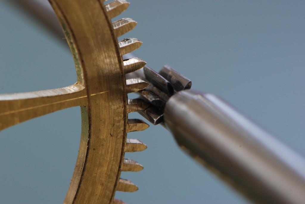
Finally the depthing and tooth shape are just right.
After feeling good about how the center wheel mates with the contrate pinion, the next step is to make and mount a collet; that’s a holder for the wheel. The collet is made from cast brass because that is what would have been used when this clock was originally made. I turned a collet to rough size and drilled a hole in the middle to fit the arbor. Then, after checking my drawing to determine the location of the collet on the arbor, I soft soldered the collet in place. One of the tricks with these collets is to leave them a big large at first, then you can turn them down to correct size once you get them on the arbor. They have to hold the wheel in exactly concentric position and the only way to do that is to turn them after they are soldered in place.
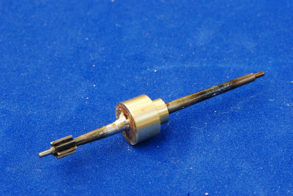
The contrate wheel with the collet soldered in place. Looks a little messy here but no worries, it will all get cleaned up.
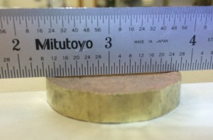
In this photos you can see that I have hammered around the edges of the cast brass because they are thicker than the middle. I also hammered on the faces of the piece around the edges both sides.
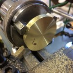
Face it off both sides.
After getting the collet in place, it is time to start turning it down to fit the wheel. But first let’s take a step back and look at the wheel making process. Start with a piece of cast brass that is hammered hard. That does not mean hammered with a lot of strength, it means hammered (sort of lightly) until the brass itself gets harder.
The next step is to cut it to the exact diameter that you want, then hollow out the middle, cut the teeth and finally finish hollowing out the middle.
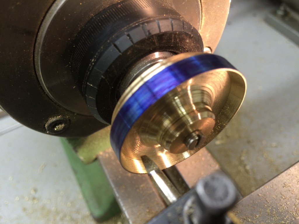
Cut the disc to diameter and hollow out the middle.
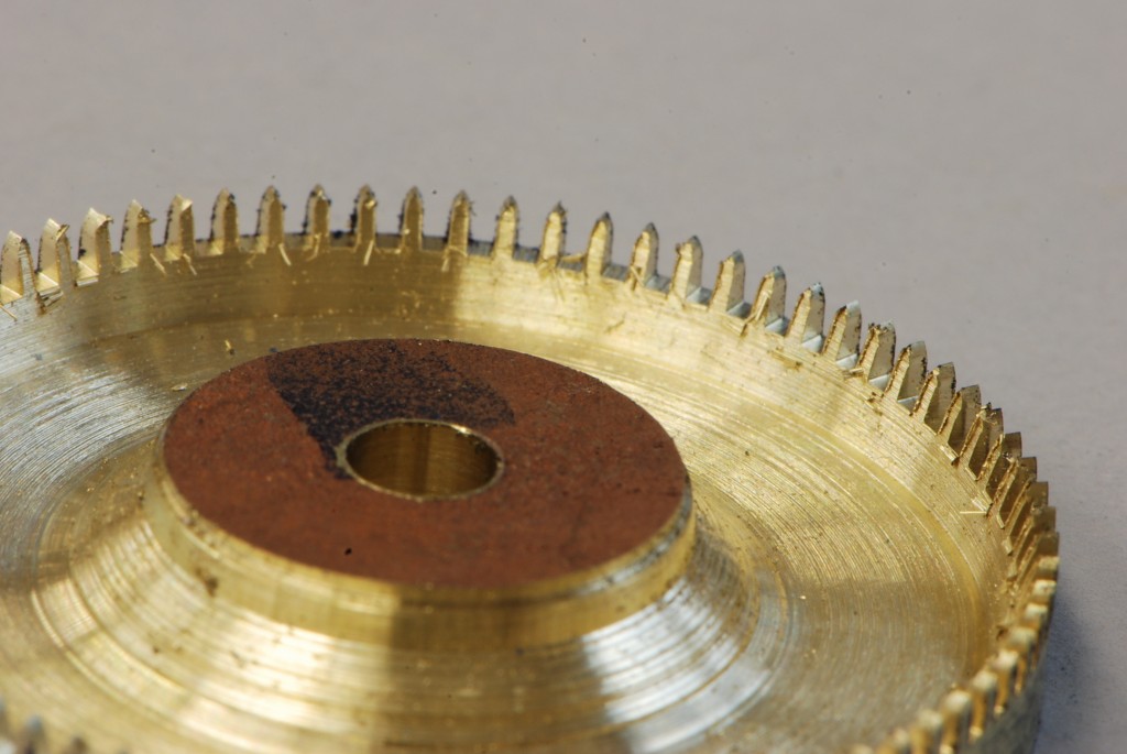
Cut the teeth. Sorry I don’t have a photo of this operation.
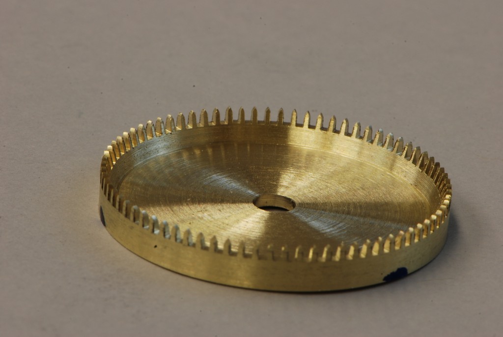
Hollow out the rest of the middle. This is not the finished wheel at this point but it is enough to allow me to put it on the collet and test it.
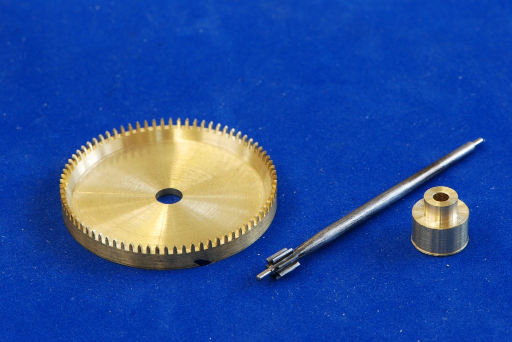
Here are all three parts of the wheel ready to go together.
Now start cutting down the collet to fit the wheel on. This is done carefully so that the wheel fits tightly on the collet. That way you can both test the wheel in position before riveting it in place and you also ensure that it will remain tight and secure after riveting. First, make a cone on the end of the collet until the wheel just fits on. That way you have a good visual gauge for the proper size. Then, start making the cone more and more like a column allowing the wheel to fit closer and closer to the seat that it has to mount against.
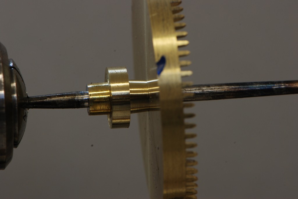
The contrate wheel just fitting onto the collet. Now I’ll start making that cone more like a cylinder so that the wheel slips further and further down.
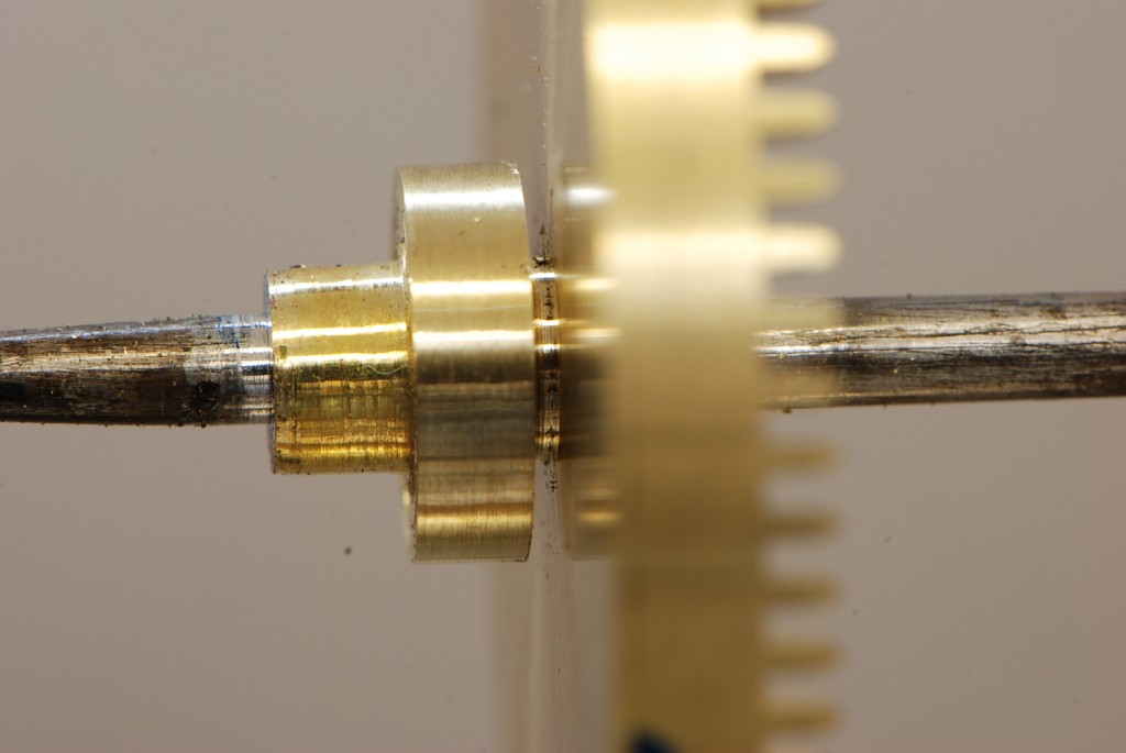
Now the wheel is almost sitting down tight.
It takes several tries of fitting the wheel then taking off a tiny bit more of the collet until you get this just right. Finally it fits on completely but still snuggly to the collet–that’s where you want it. Now you can try it in position to see how it mates with the next wheel up the train.
So put the wheels in the plates and check it out.
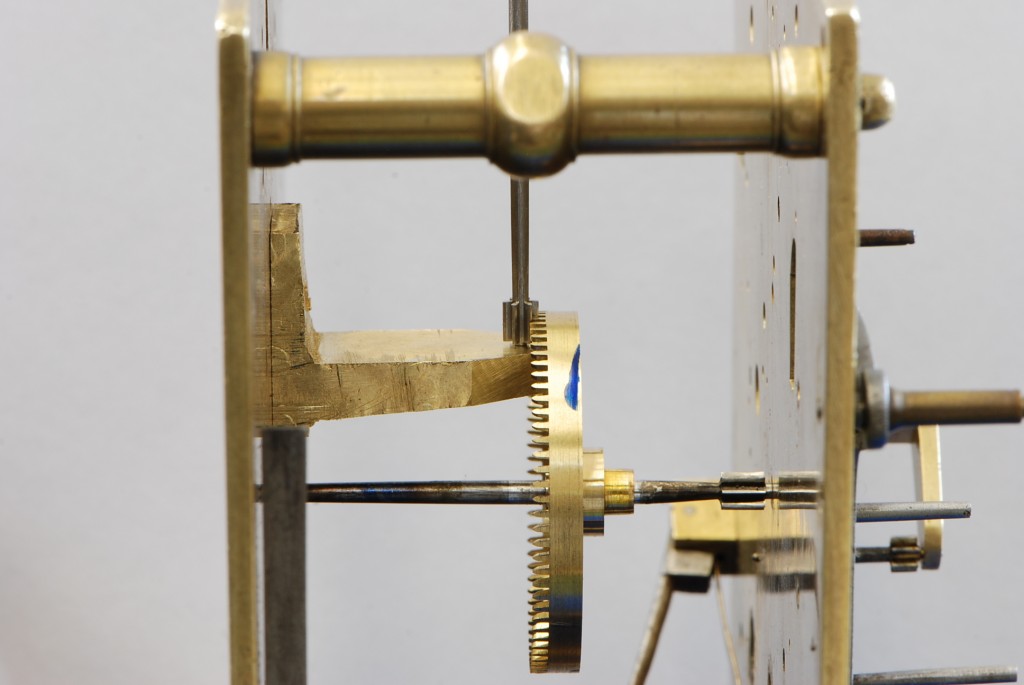
The contrate wheel meshes properly with the pinion of the crown wheel.
This worked out very well–the contrate wheel was just a bit too close to the crown wheel pinion–better too close than too far away. As my tutor says it is easier to take brass off but hard to put it back on. So now I was able to take off about a half mm from the collet and that put the contrate wheel in the perfect position.
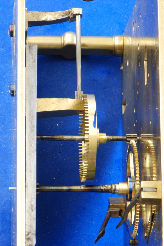
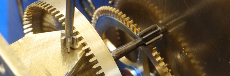
In this view, you can see the center wheel (bottom one) meshing with the contrate wheel which meshes with the crown wheel pinion.

Here’s another view from the top.
Now I have checked out two wheels and their mating pinions–time to move on to the next items in the train–that’s the crown wheel, the verge and the back-cock that holds the verge in position.
cheers,
9 comments
Skip to comment form
Mostyn, this is amazing! You explain things clearly so they are easy to understand – well, sort of! – but enough to keep reading. We remain in awe of your skill and persistence with this course. So glad you enjoy it.
Mostyn. This IS FASCINATING! Will you have the tools to create these parts on your own? I keep thi king of the men who created these and the ingenious skill and commitment
Author
Suzon,
So glad you enjoy it. I don’t have all the now but I have most of them. I do have all the parts though. So, I will adapt what I have to be able to do it. I am looking forward to setting up my own shop.
Love to you, MG
Great Job, Great explanation.
Cheers back at you!
Mike
Mostyn,
Nice job. I expect to see your clock show up at a show-n-tell when you get back. Question, since the wheel turned OK in one direction could you have just flipped it?
Author
Ken, Good question but the answer is no because the problem was the pinion, not the wheel. The only solution was to either recut the pinion (start over) or try to slightly reform the pinion. If you have good enough magnification, you can see where the problem is and focus stoning in the right place. The problem was that the pinion was hardened and tempered at that point and, as you know, hard steel is, well, hard. But I found the right grit to make the stoning go as fast as possible without being too coarse.
Thanks for the question.
Ingredible, Mostyn.!
Hi Mostyn,
Good to see you are on a steep learning curve and doing well at it !
Keep at it
David
Author
Thanks David – before long I will be back in your neck of the woods. We’ll have to be sure to get together.
Mostyn